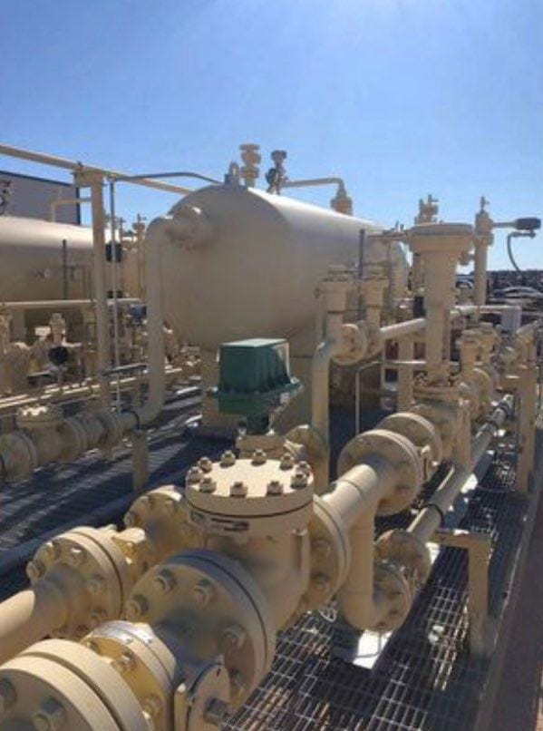
Profile
Equipment
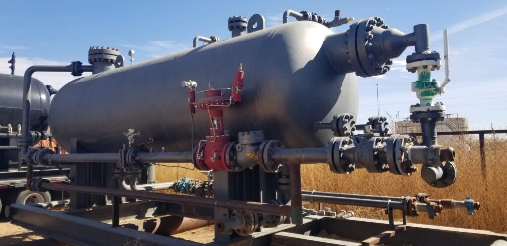
FEATURES
- Available in multiple configurations, sizes, and pressure ratings to meet individual customer needs
- Fully automated with differential pressure transmitter
- Multiple safety valves to re-direct flow in the event of over-pressurization
- Designed to meet all applicable specifications for lethal service, including H2 S
- Replaceable inlet diverter tube to increase vessel life
- External float chambers allow operators to easily check float operation during use
- Bypass capabilities allow for maintenance, repairs and replacements without having to shut in the well
- Comingling capabilities of all fluid phases provides options on how to distribute output
| SPECIFICATIONS | ||
| Equipment type | 3-Phase Production Separator | |
| Size | 60” ID x 20’ S/S | |
| Maximum Allowable Working Pressure MAWP | 2,000 PSIG | |
| Maximum Design Temperature | 200oF | |
| Minimum Design Temperature | – 25o F | |
| Material of Construction | Shell | SA 516-70 |
| Elliptical Heads | SA 516-70 | |
| Nozzles | SA-105, SA-350-LF2 | |
| Structural Skid | A572 GR-50, A500 GR-B, SA516-70 | |
| Standards | ASME Section VIII, Division 1 | |
| NACE MR0175 | ||
| ANSI B31.3 Class M (H2 S | ||
| API 12J | ||
| Class I Division I (UL, Exp) Lethal Service (H2 S) Certificates of Conformance
|
||
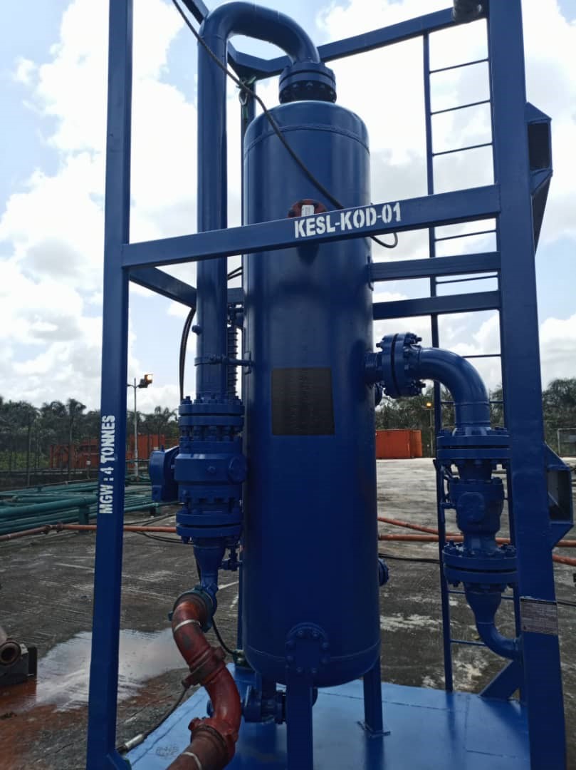
FEATURES

FEATURES
- 6” Inlet nozzle
- 6” Outlet nozzle
- Pilot Type PSV
- Hi-Lo Level Pilots with level alarm system
| SPECIFICATIONS | ||
| Equipment type | Vertical Flare Knock Out Drum | |
| Size | 30” ID x 10’ S/S | |
| Maximum Allowable Working Pressure MAWP | 1440 PSIG | |
| Maximum Design Temperature | 100oF | |
| Minimum Design Temperature | – 25o F | |
| Material of Construction | Shell | SA 516-70 |
| Elliptical Heads | SA 516-70 | |
| Nozzles | SA-105, SA-350-LF2 | |
| Structural Skid | A572 GR-50, A500 GR-B, SA516-70 | |
| Standards | ASME Section VIII, Division 1 | |
| NACE MR0175 | ||
| ANSI B31.3 Class M (H2 S | ||
| API 12J | ||
| Class I Division I (UL, Exp) Lethal Service (H2 S) Certificates of Conformance
|
||
.
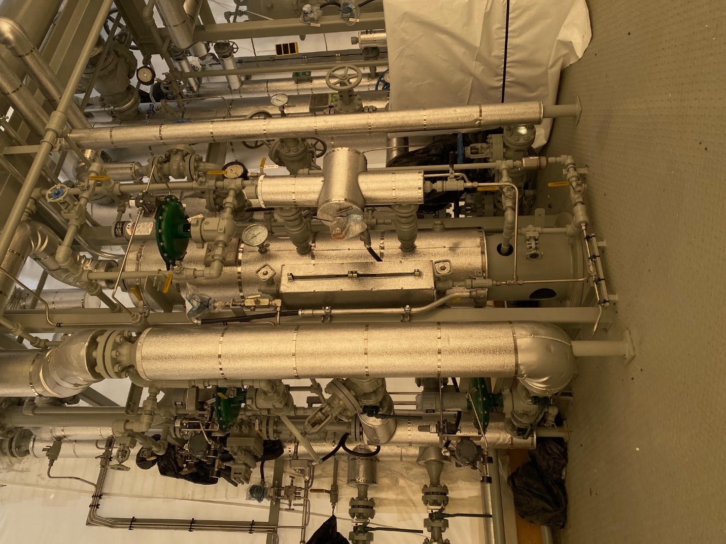
The plant is a dual train (2 X 100MMSCFD) Mechanical Refrigerated Gas Processing Unit. Designed to cool natural gas in an effort to reduce the hydrocarbon dew point of the gas to meet pipeline quality specifications, or maximize the natural gas liquid (NGL) recovery of a natural gas stream to improve the overall monetary return of a natural gas asset.
- Dual unit capability – 2 nos.100mscfd
- Low DP across the process
- Capable of providing process temperatures lower than -30ºC
- High reliability and low maintenance requirements
- Very little or low emissions
- High pressure applications
- Suitable for rich gas
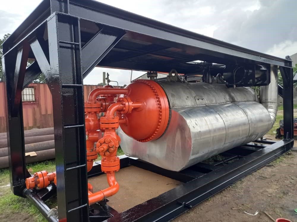
FEATURES AND BENEFITS
- Heater shell with support saddles and lifting lugs
- Dual Burner system – natural gas or diesel
- Removable U-bend type fire tube
- Removable fire tube stack
- Removable well stream flow coil
- High efficiency burner with pilot light and removable flame arrestor
- ASME code-stamped, 250 psig fuel gas scrubber with internal high level safety shutdown valve
- Fuel gas manifold with preheat coil and high and low pressure regulators
- Pre-piped fuel gas manifold with preheat coil
- Pressure gauge with isolating valve
- Temperature controller with thermowell
- Thermometer with thermowell
- Shell fill connection
- High quality enamel paint system
- Down-draft diverter
- Stack arrestor
- High bath temperature shutdown
- Energy conserving shop-installed fiberglass shell insulation with aluminum jacketing and vapor barrier
- Dry leg fuel gas thief to source fuel for remote locations
- Burner safety low (BSL)/igniter with optional solar panel
- Pilot and diaphragm actuated choke valve
- Special wellstream coils include multi-well and working pressures up to 15,000 psig
- Inlet/outlet connections may be flanged, beveled for welding, or threaded
- Heavy-duty oil-field type, I-beam skid
- Containment skid
- Expansion tank
- Special paints and coatings
- Sour gas service designed and built to NACE standards
- Customization to meet additional specifications
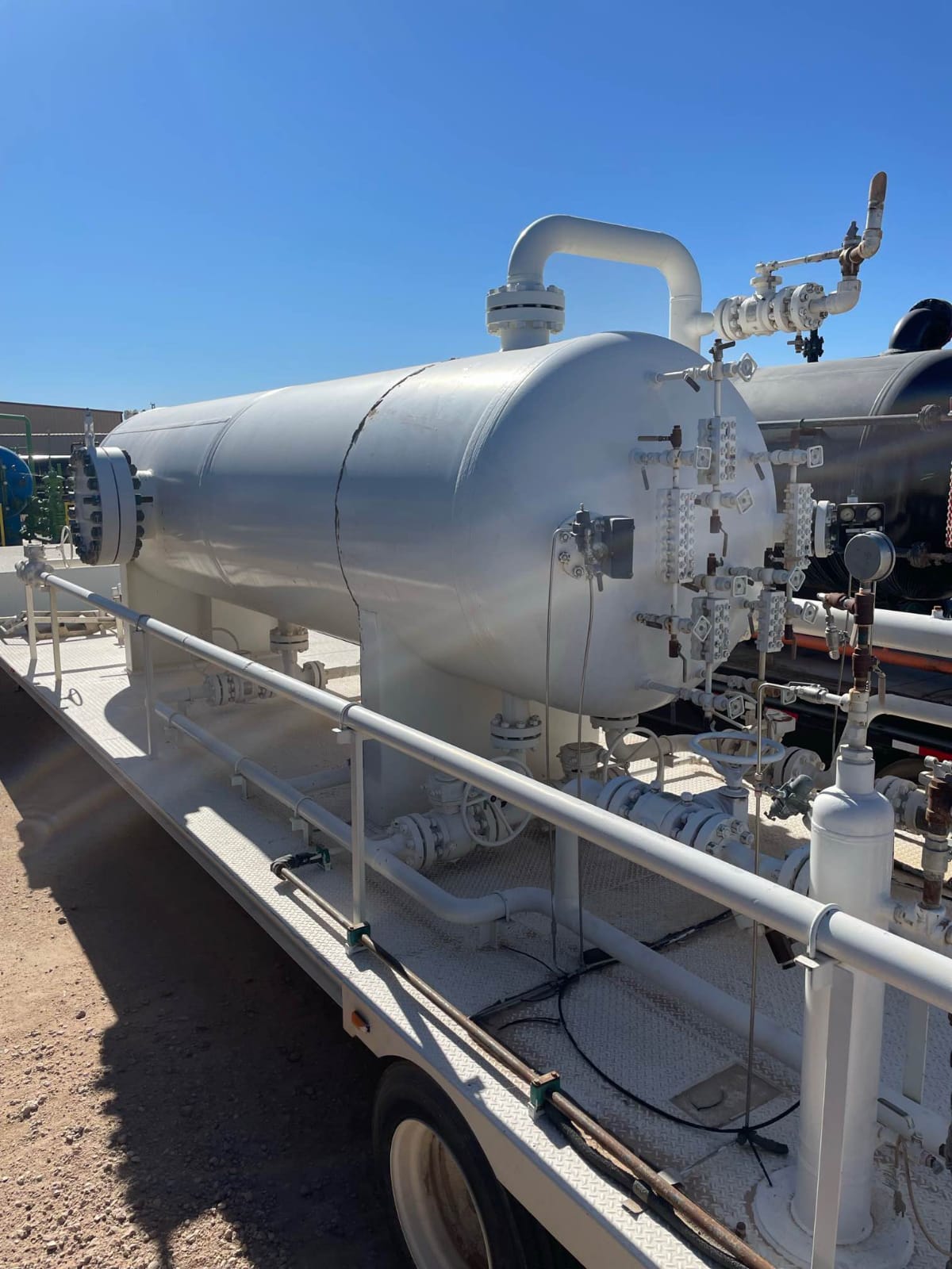
| SPECIFICATIONS | ||
| Equipment type | 3-Phase Production Separator | |
| Size | 48” ID x 10’ S/S | |
| Maximum Allowable Working Pressure MAWP | 1,440 PSIG | |
| Maximum Design Temperature | 200oF | |
| Minimum Design Temperature | – 25o F | |
| Material of Construction | Shell | SA 516-70 |
| Elliptical Heads | SA 516-70 | |
| Nozzles | SA-105, SA-350-LF2 | |
| Structural Skid | A572 GR-50, A500 GR-B, SA516-70 | |
| Standards | ASME Section VIII, Division 1 | |
| NACE MR0175 | ||
| ANSI B31.3 Class M (H2 S | ||
| API 12J | ||
| Class I Division I (UL, Exp) Lethal Service (H2 S) Certificates of Conformance
|
||

